 |
| Place of Origin: | Dongguan, China(mainland) |
| Nazwa handlowa: | HRT |
| Orzecznictwo: | ISO9001/ ISO14001/UL/RoHS/REACH |
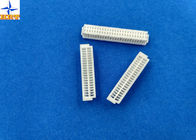
| Model Number: | A1001H-2XNP |
| Minimum Order Quantity: | 5000 pcs |
|---|---|
| Cena: | USD0.001 to 0.005 per pcs |
| Packaging Details: | Tube(pipe) with outside paper carton |
| Delivery Time: | 5 to 8 working days after payment checked |
| Payment Terms: | TT, Western Union, PayPal, L/C |
| Supply Ability: | 28 million pcs per month |
| Color: | White | Pitch: | 1.0mm |
|---|---|---|---|
| Wafer materials: | Nylon66 or PBT, UL94V-0 | Wire range: | AWG32# to 28# |
| Packaging Type: | Tube | Suitable wafer: | A1001 dual row series |
| High Light: | Connector Wire To Board,Board To Wire Connectors |
||
1, Detailed specification of product:
1.Basic information:
2. Electrical characteristic:
3. Mechanical characteristic:
Other detailed data please check the pictures as below.
2, Introduction for this series products
Please kindly notice these series product, you can buy it as a set, then we will offer you reasonable price.
| A1001 series product | ||
| Terminal | A1001-T-A | |
| Housing | Dual housing | A1001H-2XNP |
| Single housing | A1001H-NP-1 & A1001H-NP-2 & A1001HB-NP-1 | |
| Wafer | Dual rows type | A1001WV-S-2XNP & A1001WR-S-2XNP & A1001WV-SF-2XNP |
| Single row type | A1001WV-S-NP & A1001WR-S-NP | |
A1001 series demo
![]()
3,Corresponding engineering drawing & test report
Below file is our engineering drawing and testing report for further information. It's sure that it will be a
good reference for you to know this series parts clearly.
Drawing of dimension
![]()
Test report
|
1. Scope This specification covers the requirements for product performance of 1.00mm pitch wire to board connectors series.
2. Construction,Dimensions,Material & Plating See the attached drawings
3. Ratings & Applicable Wires
*: Including terminal temperature rise
4. Electrical Performance
5. Mechanical Performance
|
||||||||||||||||||||||||||||||||||||||||||||||||||||||||||||||||||||||||||||||||||||||||||||||||||||||||||||||||||||||||||
|
6. Environmental Performance And Others
7. Actuator Insertion/Withdrawal Force [Unit : kgf]
|
||||||||||||||||||||||||||||||||||||||||||||||||||||||||||||||||||||||||||||||||||||||||||||||||||||||||||||||||||||||||||
4, FAQ
Q1: Are you manufacturer or trading company?
A: We are a manufacturer with 12 years experience professional manufacturing company which specializes in producing, research and development, sales of variety of electronic connectors, terminals, wafer etc.
Q2: How to control the quality of your products?
A: Quality is life of our company. The QC staff control each procedure as per ISO9001 program. All part are100% tested before shipping.
Q3: Where is your factory located, and how can we visit there?
A: Our company is located in Dongguan city, Guangdong Province, China. It is close to shenzhen
Q4: How can I get the sample?
A: The sample is for free,but the transportation fee will be beared by customers.
Q5: What are your products applied to?
A: Our products are applied to automotive use, conmmunication equipment, industrial use, household appliance, electronics, etc.
1.5mm Pitch Battery Connectors with Tin-plated terminals 6 Poles Crimp Wire to Board Connector
Pitch 2.00mm Phosphor Brone / Tin-plated battery terminal connector
1.50mm Pitch Single Row 6 Pin Crimp Connector Battery Connectors for AWG24# To 30# wire harnesses
2.54mm Pitch Battery Connecor with Lock Bump Double Row Male Header Crimp Connectors
2.50mm Pitch Plug housing(for socket contact), SMR Connector Wire to Wire Connectors
2,00 mm Pitch Wire To Wire Connector Zagniatana obudowa gniazda dla Molex 51005/51006
Dual Row Wire To Wire Connectors Low-Halogen Molex 43025 Micro-Fit 3.0 Receptacle Housing
4.2mm Pitch Mini-Fit Plug Housing, Dual Row Wire to Wire Connector with Panel Mounting Ears
single row housing wire to board connector 1.00mm pitch 04 to 10 Pin with lock for Laptop
wire to board connector with B type lock 1.0mm pitch wire housing white color connector
Złącza 2-stykowe do 16-stykowych z przewodem do płytki Rozstaw 2,50 mm Jeden rząd z obudową zamka
Dual Row 1.00mm Pitch Wire To Board Connectors A1003H Wire Housing With Lock