 |
| Place of Origin: | China |
| Nazwa handlowa: | HRT |
| Orzecznictwo: | ISO9001/ ISO14001/UL/RoHS/REACH |
| Model Number: | A1501 wafer |
| Minimum Order Quantity: | 5000 PCS |
|---|---|
| Cena: | Negotiated |
| Packaging Details: | Carton / Paper pots |
| Delivery Time: | 5 to 8 working days after payment checked |
| Payment Terms: | TT, Western Union, PayPal, L/C |
| Supply Ability: | 1000 pcs per day |
| Product Name: | A1501WV / A1501WR | Pitch: | 1.50mm |
|---|---|---|---|
| The Number of pin: | 02PIN~15PIN | Material: | Pin: Brass/Tin-plated Wafer:PA6T |
| Row: | Single | Fire-protection rating: | UL 94V-0 |
| High Light: | Wafer Connector 2.0mm,Housing Connector |
||
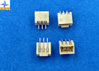
Wafer Connector Pitch 1.50mm Pin Brass/ Tin-plated wire to board connectors
Description:
1.A1501 series Wafer have A1501WV A1501WR (Single row housing suitable A11501-T series terminal )
2, Wafer used materials:PA6T , Fire-protection rating is UL 94-V0. Minimum packing quantity is 1000pcs/bag.
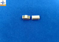
3. Single row Wafer we have 02PIN~15PIN ,The daily production capacity is 30 to 50 KPCS.
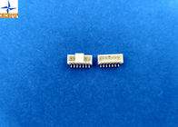
4.Terminals are stamped by Phosphor Bronze, E-Stamping beforeTin-plated , Tin-plated we calling A1501-TPe , Minimum packing quantity is 20,000pcs/Reel. The daily production capacity is 300 to 400 KPCS.
5.Terminals' wire range :AWG #22--#28insulation OD is0.90mm(Max).
| Test Description | Procedure | Requirement |
|
Contact Resistance |
Mate connectors, measure by dry circuit, 20mV max., 10mA.(Based upon JIS C5402 5.4) | 20mΩ (Max.) |
| Insulation Resistance | Mate connectors, apply 500V DC between adjacent terminal or ground. (Based upon JIS C5402 5.2/MIL-STD-202 Method 302 Cond. B) | 1000MΩ (Min.) |
| Dielectric Withstanding Voltage | Mate connectors, apply 800V AC (rms) for 1 minute between adjacent terminal or ground. (Based upon JIS C5402 5.1/MIL-STD-202 Method 301)) | No Breakdown. |
| Contact Resistance on Crimped Portion | Crimp the applicable wire on to the terminal, measure by dry circuit, 20mV (Max.)., 10mA. | 5mΩ (Max.) |
| Current rated | 3A AC/DC maximum |
| Voltage rated | 350V AC/DC |
| Withstand voltage | 500V AC/minute |
| Insulation resistance | 1000MΩ min |
| Contact resistance | 20MΩ max |
| Operating temperature | -25 - 85°C |
![]()
![]()
![]()
![]()
Environmental Performance And Others
| Test Description | Procedure | Requirement | |
| 6-1 | Temperature Rise | Carrying rated current load.(Based upon UL 498) | 30℃(Max.) |
| 6-2 | Heat Resistance | 85±2℃,96 hours (Based upon JIS C0021/MIL-STD-202 Method 108A Cond. A) |
Appearance No Damage. Contact Resistance 40mΩ (Max.) |
| 6-3 | Cold Resistance | -25±3℃,96 hours (Based upon JIS C0020) | |
| 6-4 | Humidity |
Temperature: 40±2℃ Relative Humidity : 90~95% Duration: 96 hours (Based upon JIS C0022/MIL-STD-202 Method 103B Cond. B) |
Appearance No Damage. Contact Resistance 40mΩ (Max.) Insulation Resistance 100MΩ (Min.) Dielectric Withstanding Voltage Must meet 4-3 |
| 6-5 | Temperature Cycling |
5 cycles of: a) -55℃ 30 minutes b) +85℃ 30 minutes (Based upon JIS C0025) |
Appearance No Damage. Contact Resistance 40mΩ (Max.) |
| 6-6 | Salt Spray | Tin-plated 12 hours / Gold- plated 24 hours exposure to a salt spray from the 5±1% solution at 35±2℃. (Based upon JIS C0023/MIL-STD-202 Method 101C Cond. B) | |
| 6-7 | SO2 Gas |
24 hours exposure to 50±5ppm. SO2 gas at 40±2℃. |
|
| 6-8 | NH3 Gas | 40 minutes exposure to NH3 gas evaporating from 28% Ammonia solution. | |
| 6-9 | Solderability |
Soldering Time: 5±0.5 sec. Solder Temperature: 245±5℃ |
Solder Wetting 95% of immersed area must show no voids, pin holes |
| 6-10 | Resistance to Soldering Heat |
Solder pot method Soldering time: 10±0.5 sec. Solder Temperature: 260±5℃ Solder iron method Soldering Time: 5±0.5 sec. Solder Temperature: 370℃ ~ 400℃ |
Appearance No Damage. |
Actuator Insertion/Withdrawal Force
[Unit : kgf]
| Circuits | At Initial | |
| Insertion (Max.) | Withdrawal (Min.) | |
| Single | 0.70 | 0.06 |
| 02 | 2.50 | 0.30 |
| 03 | 3.00 | 0.40 |
| 04 | 3.50 | 0.50 |
| 05 | 4.00 | 0.60 |
| 06 | 4.50 | 0.70 |
| 07 | 5.00 | 0.80 |
| 08 | 5.50 | 0.90 |
| 09 | 5.50 | 1.00 |
| 10 | 6.00 | 1.10 |
| 11 | 6.00 | 1.20 |
| 12 | 6.50 | 1.30 |
| 13 | 6.50 | 1.40 |
| 14 | 7.00 | 1.50 |
| 15 | 7.00 | 1.60 |
1.5mm Pitch Battery Connectors with Tin-plated terminals 6 Poles Crimp Wire to Board Connector
Pitch 2.00mm Phosphor Brone / Tin-plated battery terminal connector
1.50mm Pitch Single Row 6 Pin Crimp Connector Battery Connectors for AWG24# To 30# wire harnesses
2.54mm Pitch Battery Connecor with Lock Bump Double Row Male Header Crimp Connectors
2.50mm Pitch Plug housing(for socket contact), SMR Connector Wire to Wire Connectors
2,00 mm Pitch Wire To Wire Connector Zagniatana obudowa gniazda dla Molex 51005/51006
Dual Row Wire To Wire Connectors Low-Halogen Molex 43025 Micro-Fit 3.0 Receptacle Housing
4.2mm Pitch Mini-Fit Plug Housing, Dual Row Wire to Wire Connector with Panel Mounting Ears
single row housing wire to board connector 1.00mm pitch 04 to 10 Pin with lock for Laptop
wire to board connector with B type lock 1.0mm pitch wire housing white color connector
Złącza 2-stykowe do 16-stykowych z przewodem do płytki Rozstaw 2,50 mm Jeden rząd z obudową zamka
Dual Row 1.00mm Pitch Wire To Board Connectors A1003H Wire Housing With Lock